Steam Heat Exchangers and Tracing Systems: Best Practices for Design Engineers

Steam Heat Exchangers and Tracing Systems: Best Practices for Design Engineers
Alex Chu, Industrial Steam System SME, Swagelok Field Engineering
Designing a proper steam heat exchanger or steam heat tracing system first requires a full understanding of the operational characteristics where the system will function. Inadequate performance is most commonly attributed to a design engineer’s failure to consider all steam system characteristics. A thorough review should be conducted of the steam system’s operating parameters and documentation. Failing to understand the context of the application commonly results in inappropriate control or selection of system components.
Common Design and Product Selection Issues
Basic fundamentals must be considered when designing an industrial steam system to avoid premature failure or under performance. The experts at Swagelok have reviewed numerous industrial heat transfer applications in various locations and industries and have found the most common problems are caused by either incorrect component selection or improper installation practices. Example problems include:
- Unacceptable end product quality
- Premature failure of components
- Poor temperature control
- Inadequate heat transfer
- Water hammer
- Fouling of the heat transfer equipment
- Code and Standard violations
Best Practices for Steam System Design
Following some simple guidelines and proven field techniques can help you avoid the common problems associated with designing an industrial steam system. The following best practices listed throughout this article should be reviewed and implemented in your facility’s steam system design, maintenance, and specification program prior to selecting your next steam heat exchanger and tracing components.
1. Eliminate steam supply condensate build-up and carryover
A steam control valve is designed to modulate steam flow between 0 to 100%. At low or no flow scenarios, condensate can accumulate prior to the inlet of the control valve. Condensate accumulation before the valve can cause a water hammer. Additionally, any condensate passing through the steam control valve can cause premature failure of the control valve.
You can eliminate the build-up of condensate in a number of ways. Installing a drip leg prior to the valve, insulation improvement, correctly grading the steam line, or installation of a steam separator prior to the valve are just some of the methods. These methods either prevent condensation in the first place or allow the condensate to be diverted away from the control valve to be evacuated with the assistance of a steam trap.
2. Follow turndown ratio guidelines for control valves
Heat transfer components require properly sized control valves for effective process temperature control and seat life. A primary factor in selecting control valves is the turndown capability, rangeability or working range of the valve.
All valves will have a certain amount of uncontrollable flow, particularly at the extreme ranges of the valve stroke due to sealing tolerances and linearity of flow.
Following are some turndown ratio guidelines for control valves:
- Cage control = 40:1 turndown ratio provides the highest degree of controllability.
- Globe control valve = 30:1 turndown ratio.
- Regulating valve = 20:1 turndown ratio.
Incorrectly sized control valves can lead to poor process temperature control, premature wear of the valve seats and excessive noise.
3. Install pressure gauges before and after the control valve
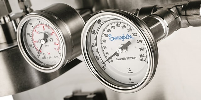
Pressure gauges provide the information necessary to understand the conditions inside the system. It’s a good practice to install a pressure gauge before and after a control valve and on the condensate return leg after the steam trap. This provides accurate data to assist in understanding the pressure characteristics of the steam passing through the steam heat exchanger. Additionally, all pressure gauges should be installed with a coil siphon (pigtail) to prevent high temperature damage and double block isolation valves to allow maintenance.
4. Install vacuum breakers
Any steam system that can be isolated from the steam supply and are not open to atmosphere must install vacuum breakers. This includes equipment such as steam lines, kettles, plate or shell and tube heat exchangers. When steam cools down inside equipment, it will condense. Since condensate can only occupy up to 1/1700th of the total volume of its mass compared when in gas phase, a vacuum will be formed.
Vacuum breakers protect steam systems from implosion when a system is shut down by preventing a vacuum occurrence. It is generally recommended that all steam equipment have an air vent and vacuum breaker installed at points designated by the equipment manufacturer.
5. Install automatic air vents
During shutdowns and maintenance, air ingresses into steam systems. Air must be purged out before the system can be returned back to service. The existence of air in a steam heat exchanger system has several detrimental effects on heat transfer and is often the cause for slow startups. The air in the system can form thin boundary layers on heat transfer surfaces—creating an insulating effect and hindering heat transfer. A film of air of only 1/1000th of an inch thick has the same effect as 13 inches of copper or 3 inches of cast iron.
Steam traps should not be relied on to vent air as they are located at the lowest point in the system and hot air tends to, instead, be trapped at the highest point. Automatic air vents are one of the most efficient ways to remove air within a steam system. An air vent fitted on the end of a steam main, or at the highest point on an equipment in conjunction with a vacuum breaker, will open when air is present.
6. Avoid backpressure within heat transfer equipment
When designing heat transfer equipment for your steam system, condensate drainage is accomplished by either gravity or a pressure differential. If possible, heat transfer equipment should be installed to promote gravitational drainage with no vertical lift before or after steam traps. This is crucial in any application that has a modulating steam control valve. Some applications do not permit gravitational drainage, and in these cases care must be taken to ensure that no undue backpressure is placed on condensate devices like steam traps or control valves. Premature failures and performance problems can occur due to unanticipated backpressure on the drain devices, which causes condensate to accumulate in the equipment. This will result in water hammer, inadequate temperature control, reduced efficiency and corrosion issues.
7. Prevent superheated steam
Typical steam heating applications require 100% quality saturated steam supply. This level of quality refers to steam containing no entrained droplets of condensate within the steam. Superheated steam, or steam at a higher temperature than its saturation point, should be prevented from entering the heat transfer process. Superheated steam contains less energy per unit volume than saturated steam and can cause performance problems if not anticipated within the original steam system design. Superheated steam supply can be conditioned by installing a de-superheater.
8. Lockout ball valves
Ball valves can provide a safe, reliable and cost-effective solution for leak tight isolation in a steam system. Ball valves allow for quick identification of isolation state through its handle orientation. Ball valves two inches or smaller can be purchased with locking handles, providing the best safety practice for a lockout or tagout. Be sure to check with your safety and inspection department to ensure compliance with any site or local regulations concerning lockout or tagout procedures within your steam system.
9. Correct selection and sizing of steam traps
There are many different mechanical designs for steam traps. Different designs cater for different applications and some are more reliable than others. For steam heat exchanger applications, a mechanical type steam trap will be best suited for modulating flow. For steam heat tracing, a variety of steam trap types can be selected depending on application needs.
Other considerations for steam trap selection is sizing based on maximum and minimum flow, requirements for priming, air venting, functional testing and mounting options. Swagelok recommends using universal mounts for smaller steam traps to allow for ease of maintenance and replacement.
The ability to test steam traps without special equipment is beneficial, especially on a closed loop return system. This can be achieved by installing a downstream bypass so a visual check of the condensate discharge can be easily and quickly performed.
10. Install a strainer to prevent foreign contamination
Contamination can become prevalent in a steam line due to corrosion and its byproducts. The contaminants can lodge within the control valve trims, isolation valve seats, and steam trap seats—causing premature failure or fouling of these components. A strainer will act as a filter, preventing any foreign materials from entering the steam system.
When installing the strainer, always install a blowdown valve with a lockout facility, and vent the discharge from the valve to a safe location. Be sure to install the strainer with the straining section in the horizontal position to prevent accumulation of condensate within the strainer body.
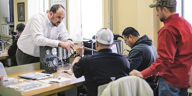
Want to learn more about how you can enhance your facility’s steam systems? Register for Swagelok’s Steam Services Training Course to gain an understanding of steam system management customized to your industry and specific needs. Contact your authorized Swagelok sales and service center to request private training at your facility.
Related Articles

Closing the Manufacturing Skills Gap: Develop a Well-Trained Team
With an aging industrial workforce nearing retirement, manufacturers are turning to younger generations to replace expert knowledge. Learn how to build an effective fluid system training program with expert advice from Swagelok.

4 Strategies to Maximize Industrial Fluid System Efficiencies
Like most plant managers and engineers, you have a lot of responsibilities—but not all the resources you need to run your plant safely and efficiently. Learn how to maximize throughput, reduce costs and avoid downtime while managing your fluid system.

Maximizing the Life of Industrial Fluid System Components
The cost of replacing an industrial fluid system component goes beyond the price of the part. Learn how to lower system costs while maximizing the life of your components with preventive maintenance tips from the professionals at Swagelok.

